 |
|
||||||||||||||||||||||||||||||||||
|
|||||||||||||||||||||||||||||||||||
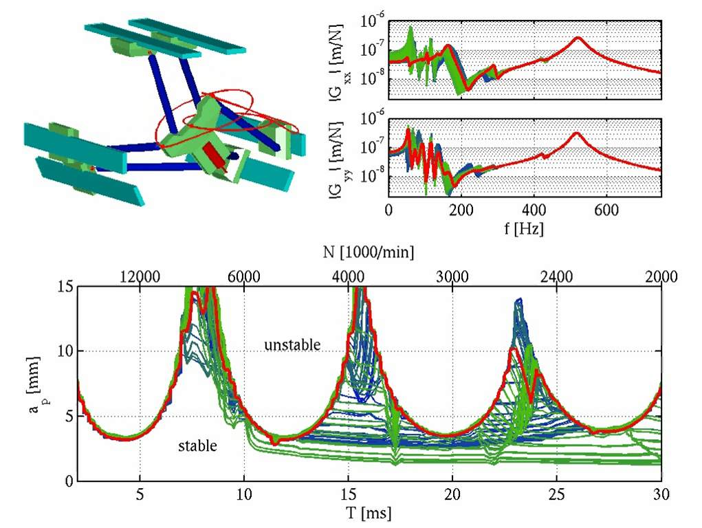
Project DescriptionIn the field of machining technology, accuracy and surface finish as well as productivity in the sense of high material removal rates of cutting processes like turning, drilling and milling is mainly restricted by the occurance of machine-tool chatter. This dynamic instability is caused by self-excited vibrations, which are induced by the repeated cutting on the same surface, the so-called regenerative effect. Modeling of these systems leads to time-delayed differential equations (DDE). In case of milling, the coefficients of the DDE are periodic time-dependent due to the changing cutting conditions of the cutting blades. Both the time-delay as well as the parameter excitation due to the time-dependency of the coefficients restrict dynamic stability of these systems. From the engineering point of view, it is important to know the stability boundary of a process depending on the relevant process parameters like spindle speed and radial and axial immersion of the tool. A possibility to facilitate the choice of safe process parameters is to provide stability diagrams showing the stability boundary in dependence of the process parameters. Furthermore, these diagrams can be helpful to investigate the influence of the dynamic system at the machine side (tool, toolholder, spindle, machine-structure) and the workpiece as well as the tool geometry on the process dynamics. There exists a variety of methods for the analysis of the dynamic stability of delay-differential equations. Assuming a linear system, the stability boundary can be formulated explicitly in the domain of technological parameters by applying Nyquist's stability criterion in the frequency domain, which allows for a very efficient computation of stability diagrams. However, the parameter excitation is mostly neglected here, resulting in a poor accuracy of stability diagrams especially for milling processes with low radial immersion ratios. A more sophisticated analysis of dynamic stability is provided by methods like the Semi-Discretization Method or the Temporal Finite Element Analysis, as both methods allow for a consideration of the changing cutting conditions of the blades during the tool rotation. In both methods, the continuous system described by the periodic delay-differential equation is approximated by a time-discrete system, which can be tested for stability by regarding its eigenvalues. Contrary to the analytical solution, the stability boundary is not given explicitly in the parameter domain there. Instead, it has to be computed implicitly by evaluating the system's stability for a large number of process parameter configurations. Beside material and process parameters, dynamic stability depends strongly on the dynamic system behavior at the machine and the workpiece side. When machining compact, strictly clamped workpieces, the workpiece dynamics can be neglected in most cases. Furthermore, the dynamic response at the machine side is often dominated by the system tool-toolholder-spindle, e.g. for massive machine structures or when using long, slender end-mills. In these cases, the dynamic behavior at the machine side can be considered to be constant during the process. Contrary to this, a significant change of dynamic behavior (eigenfrequencies, dynamic compliance) in the multi-dimensional workspace can be observed for complex 5-axis machining centers or parallel kinematic machine tools. For the workpiece, changing dynamic behavior has to be considered when complex machining trajectories are driven at light-weight structures. In these cases, dynamic stability can not be evaluated by a single stability diagram anymore. Instead, the change of the dynamic behavior both of the machine structure as well as the workpiece has to be considered during the machining process. Both the Semi-Discretization Method as well as the Temporal Finite Element Analysis are suitable for the computation of single stability diagrams of simple mechanical systems. However, when more complex models of the machine-structure or the workpiece have to be considered, the computational effort for computing series of stability diagrams along a machining trajectory reaches quickly the limits of conventional desktop computers. The goal of this project is to develop methods which allow for an efficient analysis of dynamic stability of milling processes considering complex workpiece and machine models with varying dynamic behavior. The main focus lies on the topics efficient formulation and implementation of the methods, model reduction, and adaptive computation of stability diagrams. Essential parts of this work were conducted within the project Investigation of the Influence of the Dynamics of Parallel Kinematic Machine Tools on the Stability of High Speed Machining Processes in the priority program SPP 1099 Parallel Kinematic Machine Tools of the German Research Council. The project was a cooperation between the Institute for Machine Tools IfW and the Institute of Engineering and Computational Mechanics of the University of Stuttgart. Example: Parallel Kinematic Machine Tool ParalixFor hexapod machines, the position and orientation of the end-effector is controlled by either changing the length of the struts, or by moving the base points of the struts. The geometric configuration and, therefore, the static and dynamic compliance at the end-effector depend strongly on the actual position and orientation of the end-effector in the workspace. Figure 1 shows the variation of the dynamic compliance at the tool during a tumbling trajectory, and the influence on the stability boundary of a milling process in the space of the technological parameters spindle speed N and axial depth of cut ap.
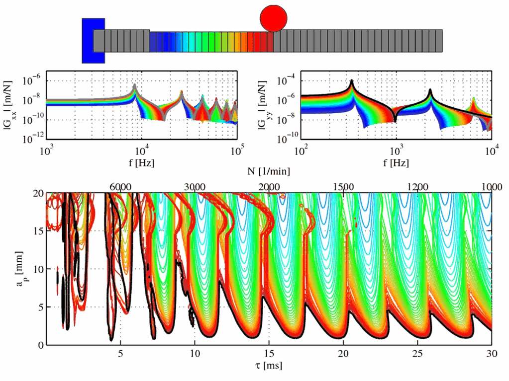
Example: Milling of a Flexible WorkpieceThe dynamic compliance of the workpiece depends strongly on the position of the process point. Additionally, the material removal of the process can cause a relevant change of the mass geometry. Both can result in a significant change of the stability boundary of the process. Figure 2 shows the dynamic compliance and the corresponding stability boundary for a milling process along a single-sided clamped elastic cantilever beam.
Contact |
| Last modified
13.10.2017 ( |