|
|
Project Description
In the field of machining technology, accuracy and surface finish as well as
productivity in the sense of high material removal rates of cutting
processes like turning, drilling and milling are mainly restricted by the
occurrence of machine-tool chatter. This dynamic instability is caused by
self-excited vibrations, which are induced by the repeated cutting on the
same surface, the so-called regenerative effect. Modeling of these systems
leads to time-delayed differential equations (DDE). In case of milling, the
coefficients of the DDE are periodic time-dependent due to the changing
cutting conditions of the cutting blades. Both the time-delay as well as the
parameter excitation due to the time-dependency of the coefficients restrict
dynamic stability of these systems.
From the engineering point of view, it is important to know the stability
limit of a process depending on the relevant process parameters like
spindle speed and radial and axial immersion of the tool. A possibility to
facilitate the choice of safe process parameters is to provide stability
lobe diagrams showing the stability limit in dependence of the process
parameters. Furthermore, these diagrams can be helpful to investigate the
influence of the dynamic system at the machine side (tool, tool holder,
spindle, machine-structure) and the workpiece as well as the tool geometry
on the process dynamics.
Modeling and Simulation of Varying Workpiece Dynamics
During machining of flexible workpieces, e.g. turbine blades, the dynamics
of workpieces is changed due to the chipping process, resulting in an
intense variation of the stability of the process. Modeling of a
continuously representation of the varying workpiece dynamics is in focus of
the work. For this purpose, methods of parametric model order reduction are
investigated and enhanced regarding feasibility, accuracy and efficiency.
Figure 1 presents a milling process of a T-shaped plate and the
corresponding stability lobe diagram of the process in the space of the
technological parameters spindle speed Ω and axial immersion
ap at different states of the machining progress.
|
|
|
Fig. 1: Effect of the machining progress regarding the stability lobe diagram.
|
Modeling and Identification of Parameter Uncertainty
In the last decade, the development of methods for the stability analysis of
linear, periodic, time-delayed differential equations made substantial
progress. Methods like the "Spectral Element Method" or the "Multi Frequency
Solution" possess excellent convergence and high efficiency. However,
simplifications in models and difficult determination of parameters lead to
uncertainty in modeling. Objective is on the one hand the investigation of
the effect of identified parameter uncertainty on stability lobe diagrams
and on the other hand the identification of parameters and parameter
uncertainty based on stability lobe diagrams, which are obtained for
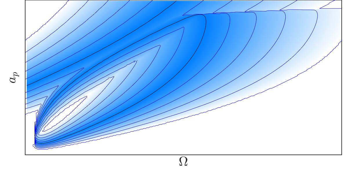
instance by experiment. Figure 2 presents the effect of an uncertain
cutting-force on the stability of a milling process in the space of the
technological parameters spindle speed Ω and axial immersion
ap.
|
|
Fig. 2: Effect of parameter uncertainty on a stability lobe diagram.
|
Related Pages
Contact
|
|